https://www.youtube.com/watch?v=Sus96TzvjT4


https://peppe8o.com/arduino-uart-communication/
Section 1: “uart-trasmitter-code.ino” code
This section contains the code explanation for the transmitter, which performs Serial.write(x). The x is the value that reads from the push button. The push button, when pressed, becomes high, which means that it becomes 1. The baud rate set for the communication is 9600. The LEDs are set here to get the value from the receiver to turn the LED on and off.
#define PB 2
void setup()
{
  Serial.begin(9600);
  pinMode(13, OUTPUT);
  pinMode(PB, INPUT);
}
void loop()
{ byte x=digitalRead(PB);
  Serial.write(x);
  if(Serial.available())
  {
  byte rec=Serial.read();
  if(rec==1)
  {
    digitalWrite(13,HIGH);
  }
  else digitalWrite(13,LOW);
  }
}
Section 2: “uart-receiver-code.ino” code
This is the section for the receiving part. Both the receiving and transmitting codes look the same as the communication is happening in half-duplex. So the commands send from the transmitter and received at the receiver by the serial.read() if the value is 1, then the LED turns on; otherwise, it remains off.
#define PB 2
void setup()
{
Serial.begin(9600);
pinMode(13, OUTPUT);
pinMode(PB, INPUT);
}
void loop()
{ byte x=digitalRead(PB);
Serial.write(x);
if(Serial.available())
{
byte rec=Serial.read();
if(rec==1)
{
digitalWrite(13,HIGH);
}
else digitalWrite(13,LOW);
}
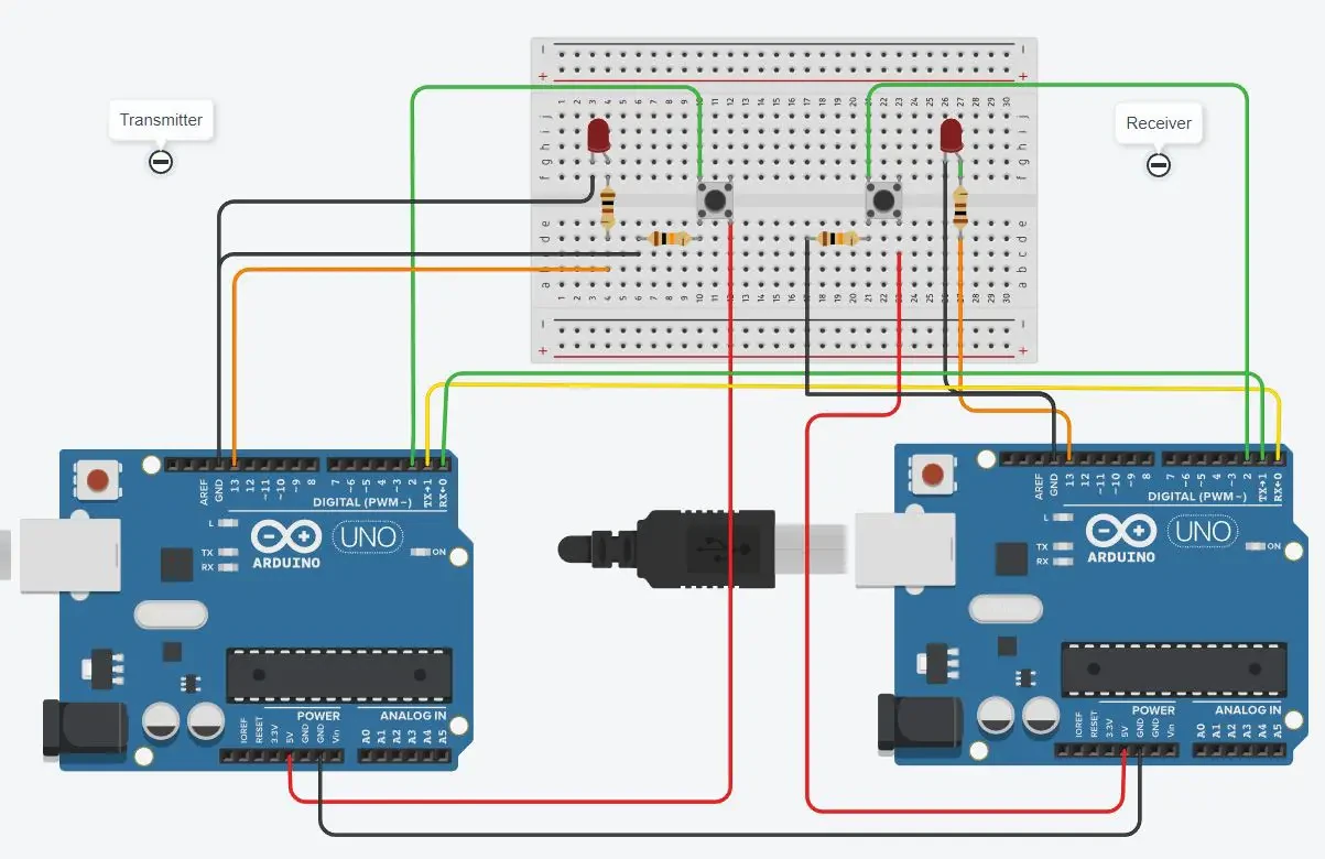
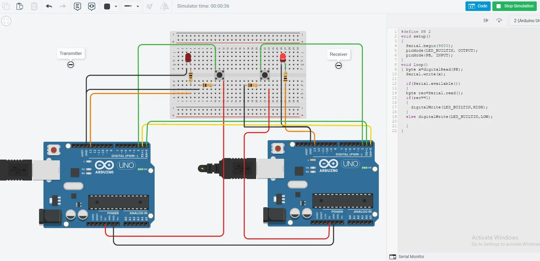
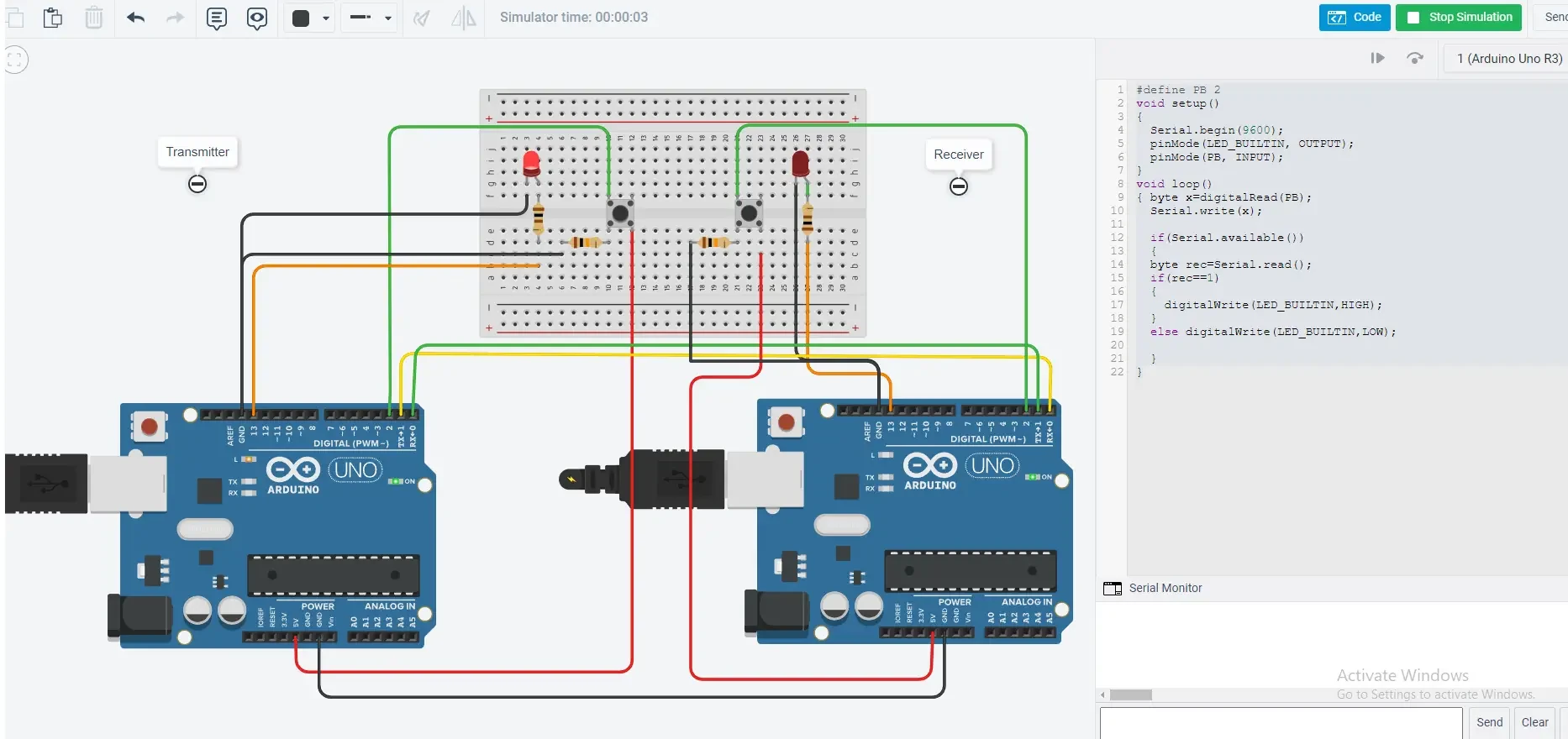
}The simulation is made to give the demo, as in the picture it can be seen that the led on the receiver side is on, which happened by pressing the button at the transmitter. Similarly, the second figure, displays that LED is on the transmitter side, in which the button at the receiver is pressed. On pressing the button, the value becomes 1, which means that the transmitted value is 1, while without pressing the button, the value is 0.
Please find more tutorials on Arduino in peppe8o Arduino archives.
Enjoy!
Umar Jamil
For any queries and help for work, please contact me at:
Whatsapp: +92-346-661-7017/ Link
Email: umarjamil0007@gmail.com

https://docs.arduino.cc/built-in-examples/basics/DigitalReadSerial/
https://www.youtube.com/watch?v=g0pSfyXOXj8
arduino pin 8 as serial input
AI Overview
Learn more
Serial and SoftwareSerial • Wolles Elektronikkiste
The line of code SoftwareSerial mySerial(8, 9); is used in Arduino programming to create a software serial object. It initializes a new serial communication port, but instead of using the standard hardware serial port (0 and 1), it utilizes digital pins 8 and 9 for serial communication. This allows you to use other digital pins for other purposes while still having a serial interface.
Here's a breakdown:
SoftwareSerial:
This is a library that enables serial communication on other digital pins of an Arduino board.
mySerial:
This is the name you've given to your software serial object. You can use this name to refer to this specific port when sending and receiving data.
(8, 9):
These are the two digital pins that will be used for the software serial port. Pin 8 is typically used for the receive (RX) signal, and pin 9 is used for the transmit (TX) signal.
How it works:
1. Include the library:
Before using SoftwareSerial, you need to include the SoftwareSerial.h library in your code: #include <SoftwareSerial.h>.
2. Initialize:
The SoftwareSerial mySerial(8, 9); line creates the object and initializes the specified pins for software serial communication.
3. Use the object:
You'll use the mySerial object (e.g., mySerial.begin(9600); to set the baud rate, mySerial.write(...) to send data, and mySerial.available() and mySerial.read() to receive data).
4. Connect:
When using software serial, you'll need to connect the RX pin of the other device (e.g., a Bluetooth module, another Arduino) to pin 8 and the TX pin to pin 9.
5. Baud Rate:
Make sure the baud rate (e.g., 9600, 115200) on both devices is the same for successful communication.
https://www.jeremyblum.com/2011/02/07/arduino-tutorial-6-serial-communication-and-processing/
https://forum.arduino.cc/t/how-can-i-control-an-led-via-the-serial-monitor/1052017
https://toptechboy.com/arduino-lesson-4-printing-over-the-serial-port/