Monday, 25 May 2020

USB HID Keyboard

http://prog3.com/sbdm/blog/yinkaishikd/article/details/49680629

Arduino analog computer keyboard (based on the USB-HID AVR-USB device)

Reprint articles, analog input

Other discussions on this post, you can also look at
Http://geek-workshop.com/thread-2303-1-1.html
Http://geek-workshop.com/thread-2310-1-1.html


Keyboard as a classic input device, the use of a lot of interaction has a special advantage, for example, we can pass the keyboard directly to the flash key events. Without the special interface such as serial port, although we can dismantle a traditional keyboard, then draw out the inside of the button, but this has a drawback, is the key cannot be dynamically and cannot be changed once multiple keys. Using the simulation model, we can set the button in the program free time and key. For example, this example is to press a button, the analog keyboard on the computer input "HELLO WORLD".

Hardware part:
Material list:
X1 Arduino
68 ohm resistor X2 (no 68 words, with 50~100 resistance is also OK)
2.2k ohm resistor X1 (no 2.2k words, with the 1.5k~2.2k resistance is also OK)
USB connecting line (one end is the USB port, the other end of the wire) x1
3.6V regulators (recommended power consumption 0.25~0.5w) x2
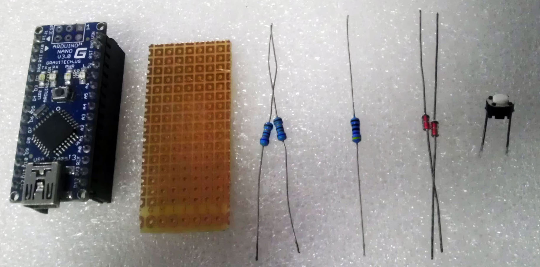
1 (1).Jpg1 (6).Jpg 

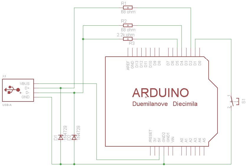
The circuit principle diagram
Arduino analog keyboard.Gif 
Circuit diagram interpretation:
1, 68 two of the resistance of the current limit and protect the role of the computer to prevent damage to the computer's USB port or the port.
2, 2.2k resistor is up pull resistance, used to distinguish the bus status. If the pull up resistor is connected to the D+ and +5v terminals, the high speed USB device is connected to the D- and +5v terminals, which is a low speed device. The keyboard transfer rate is not high here, received D- as low speed equipment can be.
3, D+ and 3.6V on the D- regulator diode D1 and D2 play a role in limiting the level of the data line. Because in the USB specification, the data line D+ and D- on the level range is 3.0V to 3.6V, and the output level of the AVR microcontroller is Vcc. If the microcontroller Vcc is 5V, in the absence of D1 and D2 will cause the level does not match, will result in a lot of computer can not correctly identify the USB device. If the user system Vcc in between 3.6V to 3.0V, you can omit the two voltage regulators. From here we can see that the user system of Vcc must be higher than 3V.
4, due to the low speed AVRUSB is needed is the 1.5MHz clock, and the single chip every 8 instructions can accurately complete a data bit collection. So AVRUSB minimum microcontroller clock frequency is 12MHz. And can use the clock frequency of 12MHz, 12.8MHz, 15MHz, 16MHz, 16.5MHz, 20MHz, the other is not supported. So if the use of the minimum system to produce this analog keyboard, then 8MHz, ATMega8L can not be used.
-- -- -- -- -- --
Software part:

Arduino support library file:
Http://soft1.wmzhe.com/download/ Ino/UsbKeyboard.zip...
 UsbKeyboard.zip (112.45 KB, download times: 1415) 
After the file is downloaded to the Arduino compiler to extract the libraries folder below.
be careful

1, UsbKeyboard library, usbconfig.h which can change the USB pin definition, the following is given a probably explain (below the PORTD refers to the AVR microcontroller PORTD, to queryArduino schematic diagramIn order to get the Arduino which pin:

USB_CFG_IOPORTNAME D #define
USB input and output pins using AVR microcontroller PORTD, if the change to B is to use PORTB
USB_CFG_DMINUS_BIT #define 4
D- USB connected to the PORTD fourth bit PD4, corresponding to D4 Arduino
USB_CFG_DPLUS_BIT #define 2
D+ USB connected to the PORTD second bit PD2, corresponding to D2 Arduino
USB_CFG_PULLUP_IOPORTNAME D #define
USB on the pull pin to use the PORTD microcontroller AVR, if the B is to use PORTB
USB_CFG_PULLUP_BIT #define 5
USB on the pull resistor connected to the PORTD fifth bit PD5, corresponding to D5 Arduino


2, in the UsbKeyboard Library of UsbKeyboard.h, a simulation of key table
KEY_A #define 4
KEY_B #define 5
KEY_C #define 6
KEY_D #define 7
KEY_E #define 8
Etc.. But not complete. After testing, the basic keyboard can simulate almost all keys (Power, Sleep, Pause does not seem to).
For example, the direction of the right left and bottom right corresponding to the 79,80,81,82 number. Written in
UsbKeyboard.sendKeyStroke (79);
UsbKeyboard.sendKeyStroke (81);
Etc.. As a result of finishing the trouble, you can download the KeyboardTest software to test different digital own key.

Program sample:
The following example demonstrates the application of the virtual keyboard with Arduino examples. Open Notepad, and then the D12 GND pin and connected to the Arduino, it will print the words WORLD HELLO.
ARDUINO codecopyPrint
  1. *
  2. Arduino analog keyboard Ansifa by
  3. 2012.6.8
  4. Function Description: insert this analog keyboard, open Notepad, and then press the button, you can print out the WORLD HELLO in Notepad
  5. Connection method:
  6. Src= http://www.geek-workshop.com/forum.php "<img? Mod=image&aid=5359&size=300x300&key=e9fa5559e6d5724d51f770bc6c55b941&nocache=yes&type=fixnone" border= "0" aid= "attachimg_5359" alt= "" ""
  7. D2 Arduino after 68 resistance, then USB line D+
  8. D4 Arduino after 68 resistance, then USB line D-
  9. D5 Arduino 2.2k after the resistance, then USB line D-
  10. D2 Arduino connected to the 3.6V regulator tube to GND
  11. D4 Arduino connected to the 3.6V regulator tube to GND
  12. +5v connect USB line VCC
  13. GND connect USB line GND
  14. D1 Arduino connect a switch to GND
  15. Attached: USB line order color (due to the different production plants, not necessarily accurate, for reference only)
  16. *USB mouse: *USB interface
  17. White <->VCC red <->VCC
  18. Orange <->D- white <->D-
  19. Green <->D+ green <->D+
  20. Blue <->GND black <->GND
  21. * /
  22. #include"UsbKeyboard.h"
  23. IntKEYPIN =One;/ / access keys in the D1 pin can be any pin
  24. Void Setup()
  25. {
  26. TIMSK0 &=!(OneTOIE0);/ /
  27.   PinMode(KEYPIN,INPUT);
  28.   DigitalWrite(KEYPIN,HIGH);
  29. }
  30. Void Loop()
  31. {
  32. UsbKeyboard.Update();
  33.   If(DigitalRead(KEYPIN)= =HIGH)
  34.   {
  35.     Delay(One hundred);
  36.     If(DigitalRead(KEYPIN)= =LOW)
  37.     {
  38. UsbKeyboard.SendKeyStroke(KEY_H);
  39. UsbKeyboard.SendKeyStroke(KEY_E);
  40. UsbKeyboard.SendKeyStroke(KEY_L);
  41. UsbKeyboard.SendKeyStroke(KEY_L);
  42. UsbKeyboard.SendKeyStroke(KEY_O);
  43. UsbKeyboard.SendKeyStroke(KEY_SPACE);
  44. UsbKeyboard.SendKeyStroke(KEY_W);
  45. UsbKeyboard.SendKeyStroke(KEY_O);
  46. UsbKeyboard.SendKeyStroke(KEY_R);
  47. UsbKeyboard.SendKeyStroke(KEY_L);
  48. UsbKeyboard.SendKeyStroke(KEY_D);
  49. UsbKeyboard.SendKeyStroke(KEY_ENTER);
  50.     }
  51.   }
  52. }
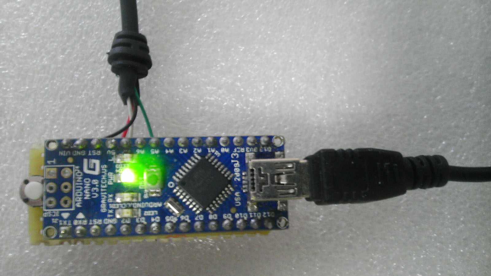
Note that the first plug in the Arduino data line, the program will be written to Arduino. Then unplug the data line, the analog keyboard USB line received a computer, you can use.

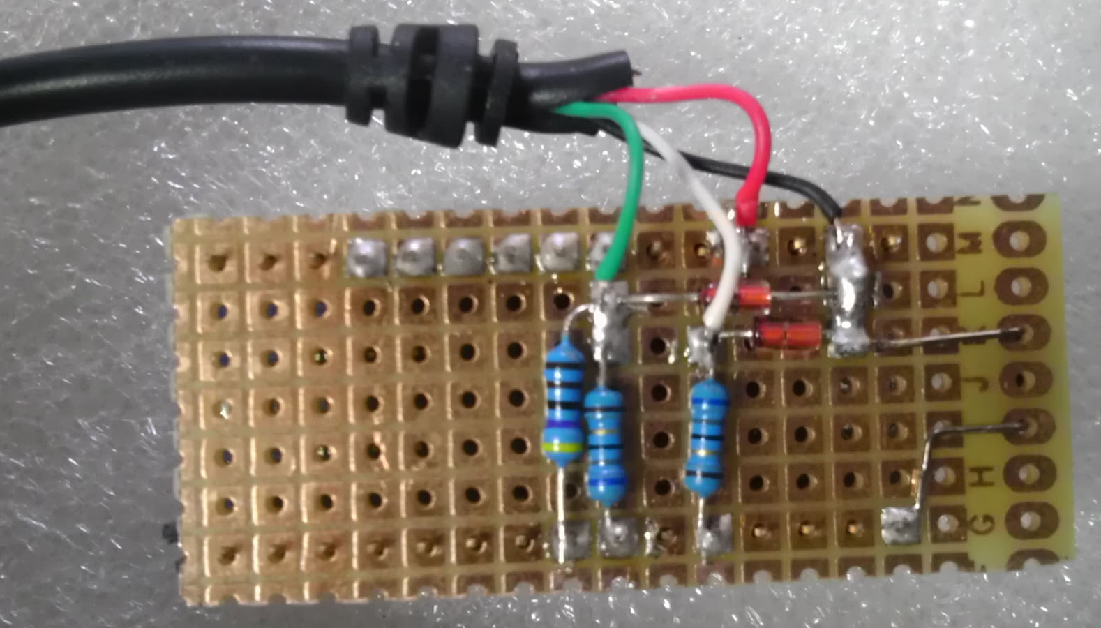
The following casually point physical map

A positive and negative side
Arduino-1.jpg1 (4).Jpg 

Insert data into the program into the data line Arduino:
1 (5).Jpg
top
Zero
step

No comments:

Post a Comment